Lab Objective
We equipped the robot with two VL53L1X time-of-flight distance sensors so it can perceive obstacles and react to the world.
Pre-lab
The default I2C sensor address listed in the datasheet is 0x52.
Both sensors have the same address. To use two at the same time, we need to shut one off, change the other’s address at runtime, and turn the first one back on, every time we start up the robot. An alternative method is to shut off one sensor every time we want to read from the other one, but this would introduce unnecessary overhead.
My plan is to put one sensor on the front of the robot and one on the back. The robot will miss any obstacles which are directly to the sides, but could still see them if it turns up to 180 degrees.
My plan for connecting components was this:
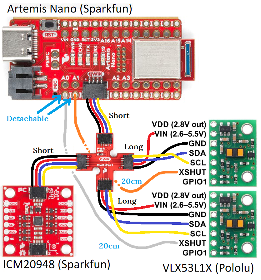 The two long QWIIC cables would be used to connect each TOF sensor to the
breakout, and the two short QWIIC cables would connect the IMU (in a later lab)
and the Artemis to the breakout. Two 20cm grey and orange wires would be
soldered to the XSHUT pins on each TOF sensor, and these would be connected to
detachable connections on the A0 and A1 pins. The 4 QWIIC wires would be
soldered to pins on each TOF sensor: black to GND, red to VIN, blue to SDA, and
yellow to SCL.
Lab Tasks
QWIIC Connection
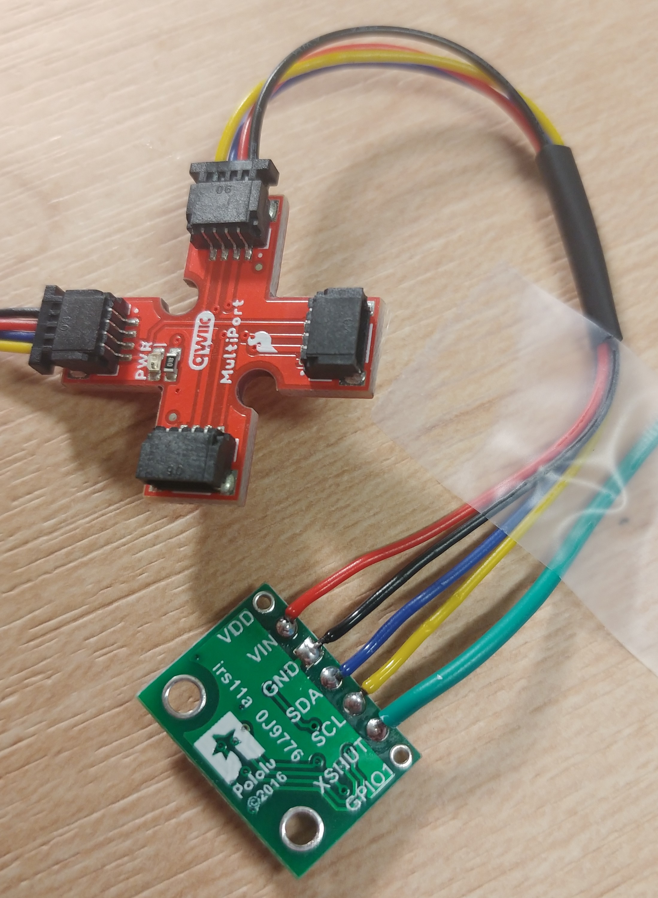 As planned, except the grey and orange wires were replaced with green and yellow
wires, and I soldered them to the A2 and A3 pins on the Artemis instead of using
detachable connectors on the A0 and A1 pins. I couldn’t find female connectors
in the lab so I gave up on making detachable connections, and figured I wouldn’t
need to remove these wires ever.
Scanning I2C Channel
I uploaded Apollo3>Example05_Wire_I2C.ino to the board, which printed this to the serial monitor:
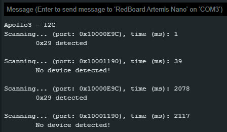
By modifying the code we see that the “No device detected” messages are printed
when we call testPortI2C(Wire1), and that we always detect the device if we
comment out that line.
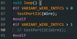
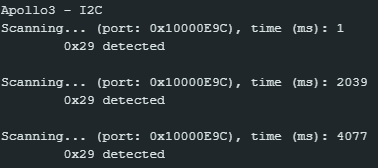
After doing this and disconnecting the TOF sensor from the QWIIC breakout, the board always prints that no device is connected, confirming that the TOF sensor has an I2C address of 0x29.
This is different from the default address 0x52 given in the documentation for this sensor. It could be that the default address changed since 2018, when the documentation was published.
Getting TOF Sensor Data
The three distance modes available in the sensor are short, medium, and long. Longer-distance ranging is more impacted by ambient light, so the ideal choice for accurate measurements is to use the shortest distance mode possible. The final robot should probably use the short-range mode, since there will be ambient light in the testing environment.
To test the accuracy of the sensor at different distances, I set up the sensor on a vertical surface with a measuring tape and wrote code to print the average of several distance samples:


I recorded the sensor’s measured distance while holding a cardboard box at intervals of 100mm, and got the following results:
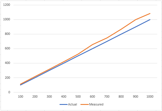
Some of the error is because my sensor wasn’t perfectly aligned with the start of the measuring tape. The error also seems to increase the further away an object is. This makes sense, since distant objects take up less of the sensor’s field of view, meaning a reading is less precise.
Two Sensors
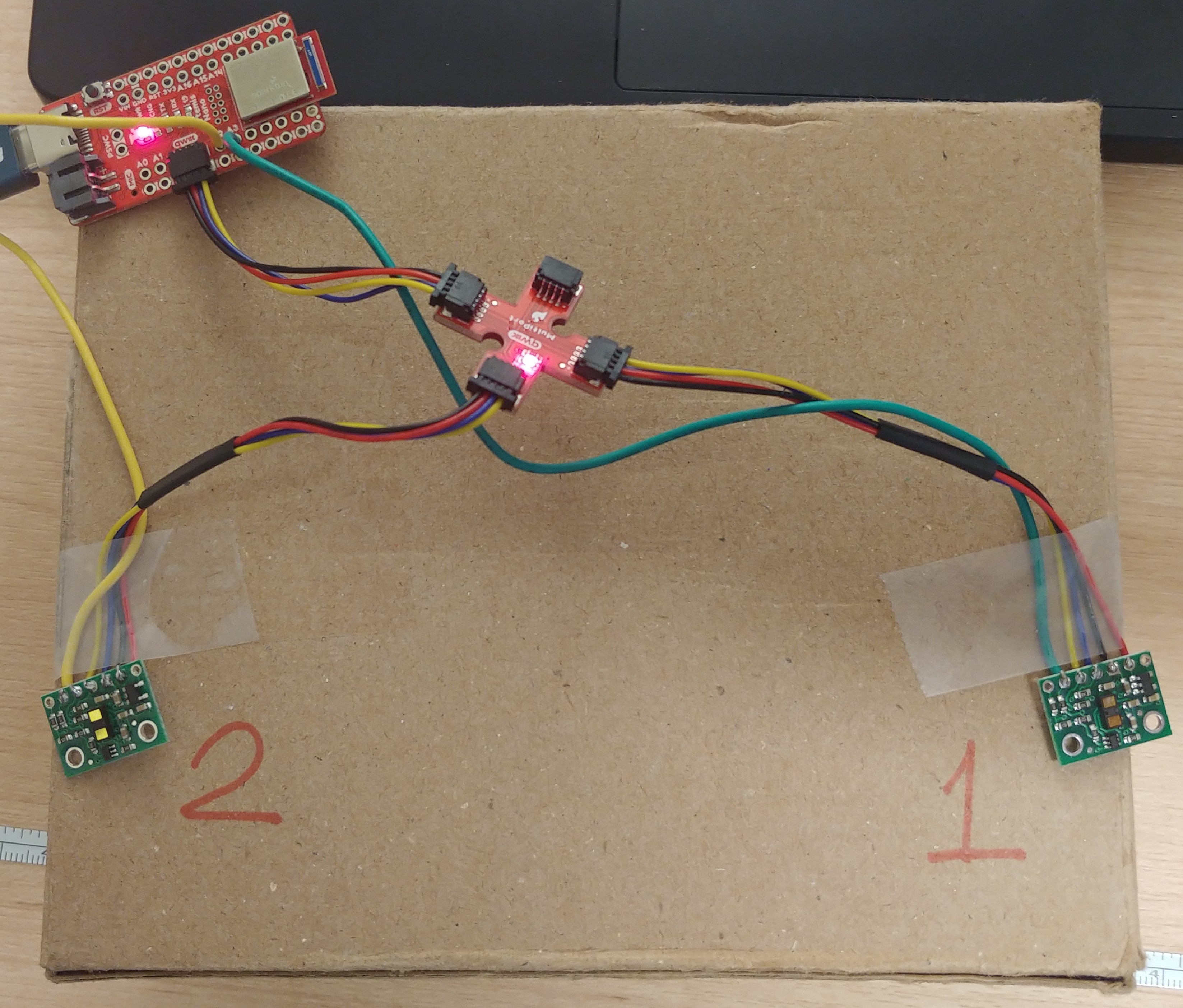
To make both sensors work at the same time, I defined both as separate variables, and deactivated one using its corresponding shutdown pin while changing the address of the other.

In setup() I added:
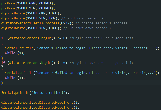
In loop() I changed the code to read and print data from both sensors:
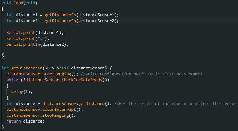
I ran this code and opened SerialPlot to see the data change over time as I moved my hands over the two sensors separately.
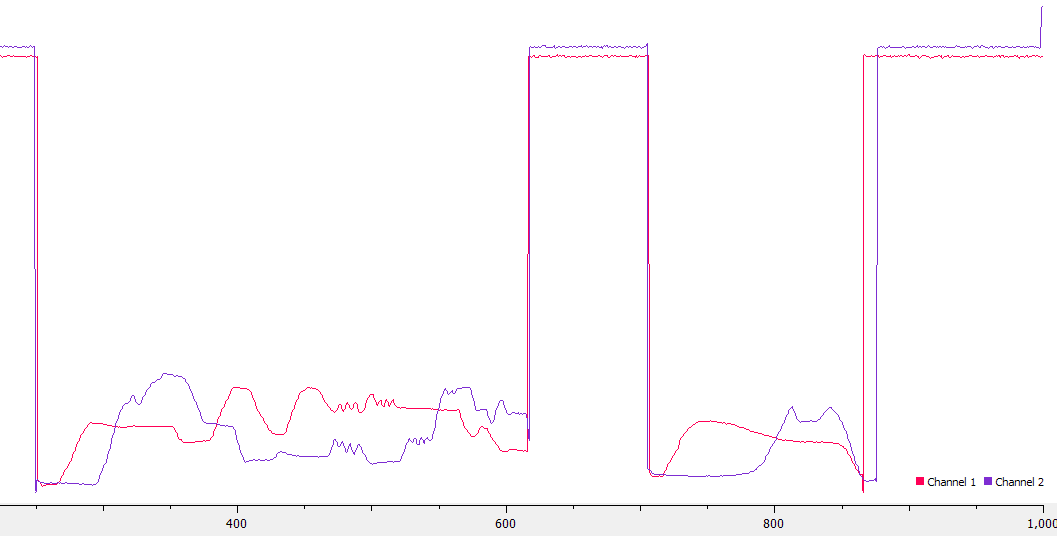
This confirmed that I am able to read from both sensors separately on the same I2C channel using different addresses.
Sensor Speed
To stop the program from halting while it waits for sensor data, we can rewrite the loop to keep going if a sensor doesn’t have data ready:
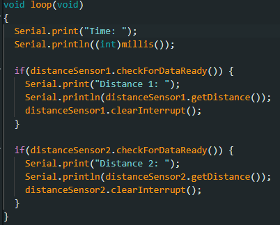
I also moved the startRanging() calls into setup(). This code produces
output that looks like the following:
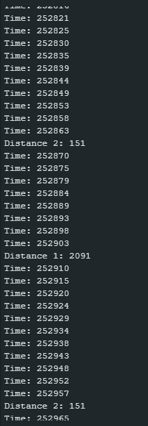
Every loop consistently takes 4 or 5 ms to execute, unless one of the sensors has data ready, in which case the loop takes 7 or 8 ms to execute. The limiting factor in this loop is probably the time it takes to print a string to serial. The limiting factor in getting data from the distance sensors is waiting until they have data ready.
Data over Bluetooth
(I haven’t done this task yet, because I ran into Bluetooth issues and ran out of time.)
Additional Tasks
Discussion on infrared transmission based sensors
We are using a time-of-flight IR sensor, but there are also amplitude IR sensors and triangulation-based IR sensors.
Amplitude sensors rely on the inverse-square law, which says that the amplitude of a wave falls off as 1/r^2 where r is the distance from the wave source. Comparing the amplitude of a reflected wave to the magnitude of the emitted wave lets the sensor calculate the distance to an object. This kind of sensor is very cheap and simple, since it only requires a transmitter and a photo diode detector, but works best at short range, and is sensitive to color and texture.
Triangulation sensors emit a wave at an angle and measure the reflected wave with an array of diodes, using the angle and the distance between the highest-magnitude diode and the emitter to calculate the distance to the object. These sensors are still cheap but not as cheap as amplitude sensors, and are medium range. They are less sensitive to color than amplitude sensors.
Time-of-flight sensors, which we are using, use the phase difference between emitted and reflected photons to determine the time between emission and detection, calculating the distance to the object using the speed of light. This kind of sensor is the least sensitive to texture, color, and ambient light, but may be more expensive.
Sensitivity of the TOF sensor to colors and textures
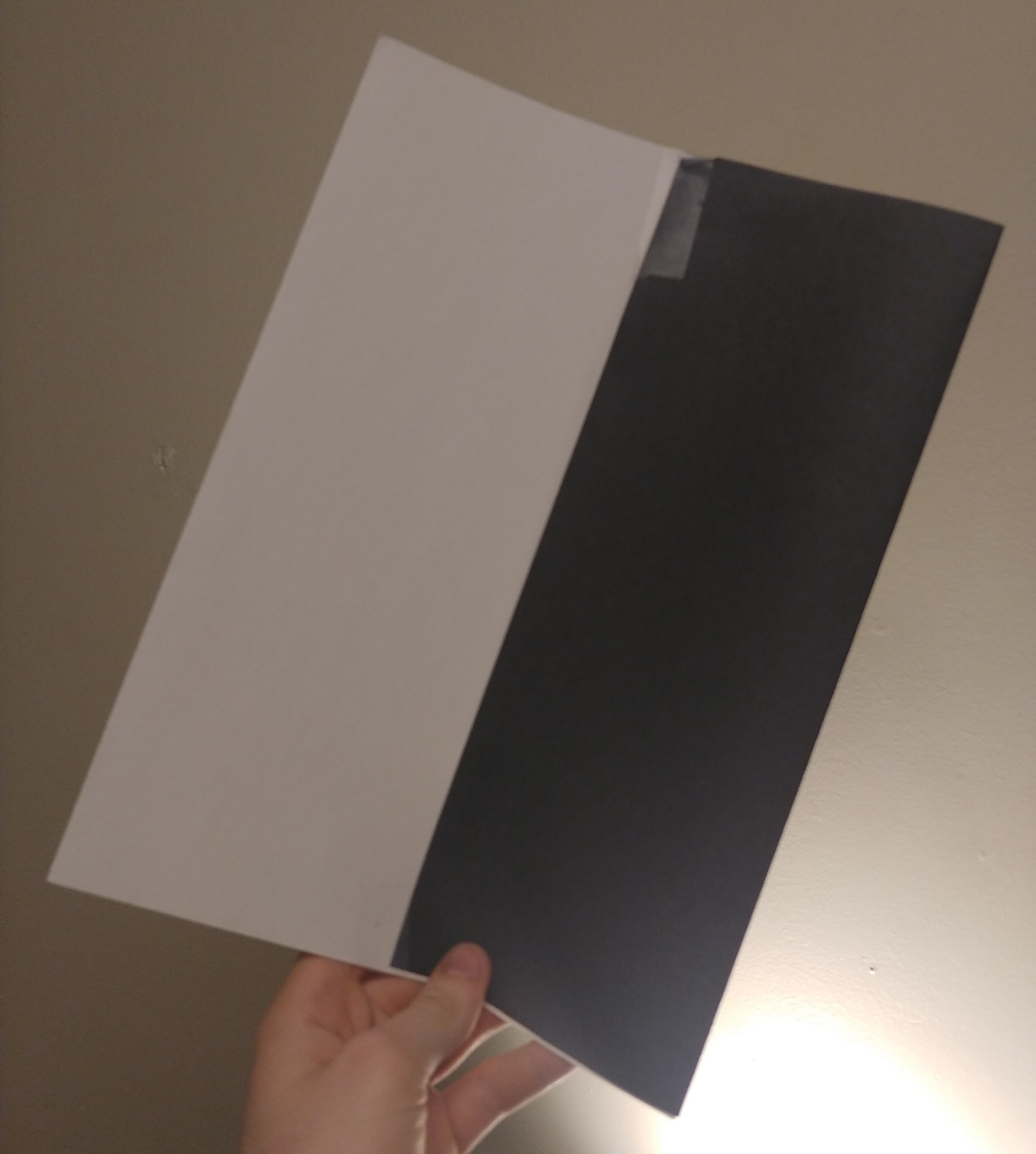
To test the sensor’s sensitivity to object color, I taped together two pieces of construction paper, one black and one white, and held the combined piece at a constant distance from the sensor. I then moved the paper perpendicularly, so that it remained at the same distance to the sensor and only the color of the paper in front of the sensor changed. The distance measurements did not change significantly, at any distance. I can conclude that the TOF sensor is not very sensitive to surface color.
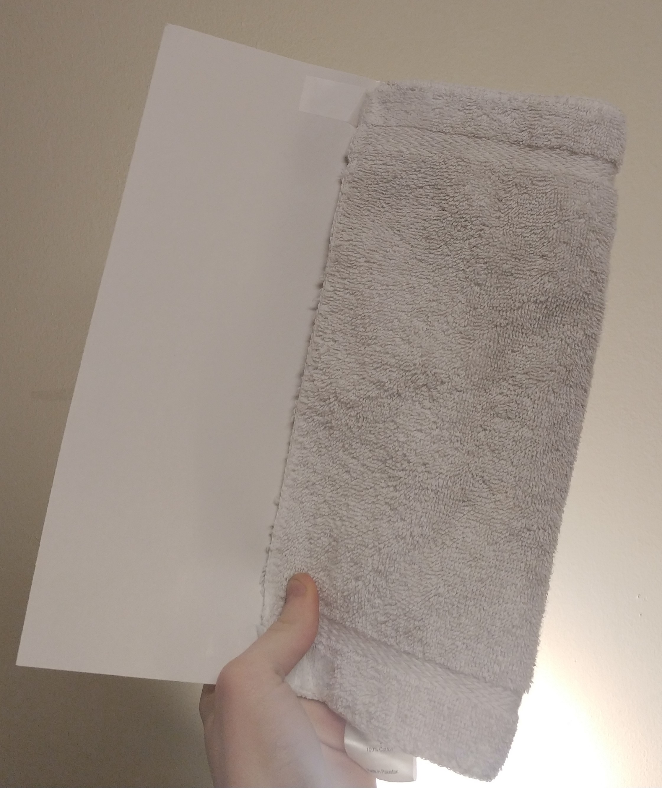
To test the sensor’s sensitivity to texture, I repeated the above with a coarse towel instead of smooth construction paper. The distance readings still remained mostly the same, so the sensor isn’t very sensitive to surface texture.
I thought the sensor shouldn’t be able to handle transluscent objects, since it works by emitting light and receiving reflected light. I placed a transluscent plastic lid 10 cm in front of the object and got wildly inconsistent readings.
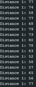
This confirms that one weakness of the TOF sensor (and all IR sensors) is objects which transmit much more light than they reflect.